Expert Spring Machine Factory - Recruit Distributor
Operating Instructions for Jingye Camless Spring Machine
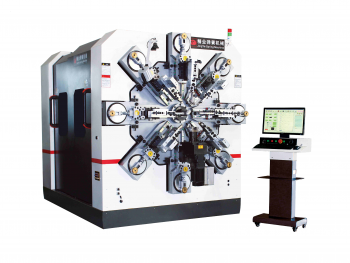
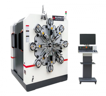
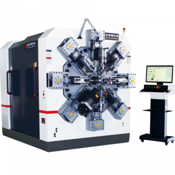
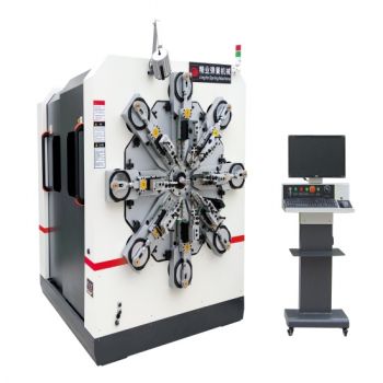
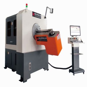
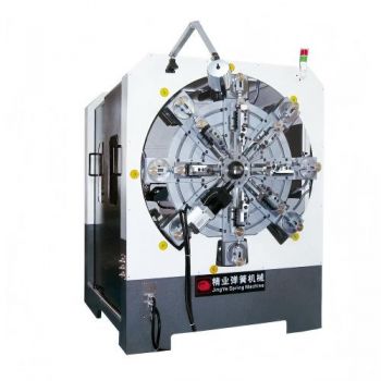
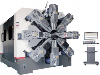
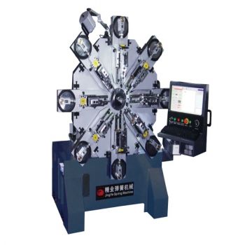
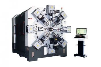
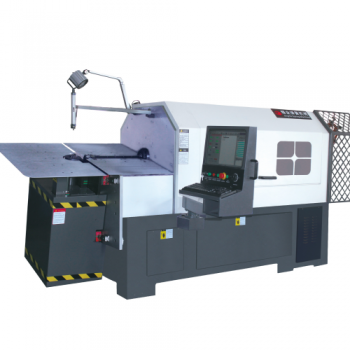
The camless CNC spring forming machine is a new type of multi-functional universal CNC spring forming machine, representing the inevitable trend in the future development of CNC spring machines. Its functions and features are unmatched by traditional cam-type CNC spring forming machines, and it is widely used in developed regions. The camless CNC spring forming machine uses more than 10 servo motors for control, employing a unique rocker arm-less design. Eight servo motors independently control eight claw arm stations. In addition, the wire feeding system, core rotation system, wire turning system, and bending system are all driven by independent motors, making machine debugging faster and more convenient.
Camless CNC spring forming machine operation sequence:
1. Confirm that the power is off.
2. Wipe the machine parts on the machine platform.
3. Install the tool holder and adjust it to the required position according to the working conditions: Gently push the tool holder towards the axis along the slide rail by hand, and fix the tool holder in the infeed position with two tool holder fixing screws.
Precautions: This machine is equipped with the following tool holders: 3 sets of left movable tool holders, 2 sets of right movable tool holders; 1 set of left moving tool holder, 2 sets of right moving tool holders; and 1 set each of left, center, and right moving tool holders. Users should select the appropriate setting based on their spring processing needs.
4. Install accessory equipment, such as impact blocks, tension spring hooks, etc.
Precautions: Impact blocks, tension spring hooks, and other accessory equipment are only used for movable tool holders. These accessories are not available for moving tool holders. The illustration shows the equipment configuration for moving tool holders. (Please install according to the process to prevent injury to personnel and machinery.)
Camless Computerized Spring Machine Working Arrangement Function and Adjustment Instructions:
1. This working arrangement is a crank-slider arrangement. This arrangement converts the rotational motion of the motor into the linear motion of the slider via the crank disc and connecting rod.
2. Adjusting the connecting rod length: Loosen the four locking screws, and turn set screw 1. Turning it clockwise increases the connecting rod length; turning it counterclockwise decreases the connecting rod length.
3. Adjustment of the die cutter's feed angle: ① Control angle adjustment: There are six fastening screws on the slide block, and one set screw at each end of the slide block. Loosen the six fastening screws on the slide block, and turn the set screws at both ends of the slide block (the turning directions of the set screws at both ends are exactly opposite). After adjusting the die cutter's control angle to the appropriate position, tighten the fastening screws. ② Vertical angle adjustment: There are two adjustment screws on the tool holder. These two adjustment screws are used to adjust the vertical angle of the cutter, i.e., the pitch angle. Turning the rear adjustment screw in the opposite direction and the front adjustment screw in the forward direction will raise the cutter upward; turning the rear adjustment screw in the forward direction and the front adjustment screw in the opposite direction will lower the cutter downward. This adjustment is not available when moving the tool holder.
Precautions: When working or adjusting the machine, please disconnect the machine first and ensure that the power is off.